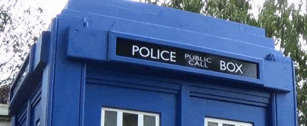
Couple Running to Police Box Drawing
Introduction
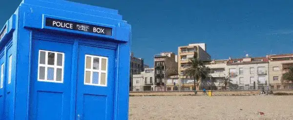
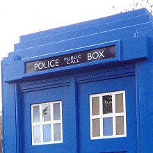
The London police box was a little shed type structure used mainly as a communications base for patrolling police officers prior to the age of mobile telecommunications.
Typically, the boxes were blue. They allowed patrolling officers to keep in bear upon with the station via a phone.
The boxes had a light on top that would flash to alert the patrolling officeholder that the phone was ringing.
The public could also employ the telephone in an emergency.
The Metropolitan Police introduced law boxes throughout London between 1928 and 1937.
The Constabulary Box was the inspiration for the well known TARDIS.
The TARDIS is a time automobile featured in the very popular British science fiction television series "Doctor Who" that was first aired in 1963
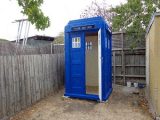
It is a very solid structure suitable non only for show, but also for many practical uses. Information technology is big and strong plenty to exist used every bit a garden shed
The designs of the TARDIS props used in the television set series have changed many times only none has really been an exact copy of the existent police box.
Description
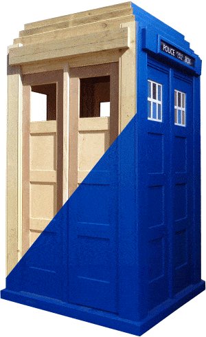
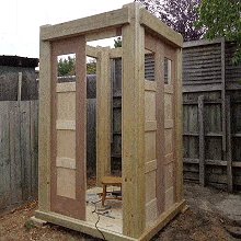
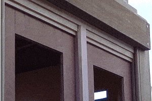
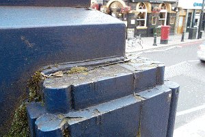
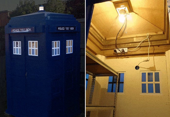
This police box is a very solid structure.
It is my take on the 1929 Mackenzie Trench blueprint law watch box, very like to (and the same size as) the Constabulary Watch Box that sits outside Earls Court Railway Station in London.
The police box outside Earl'southward Courtroom tube station in London was built in 1997 and based on the 1929 Mackenzie Trench blueprint.
The law box here is not a prop.
Information technology is a very solid construction suitable not only for show, merely besides for many practical uses. It is big and strong enough to be used as a garden shed to store garden tools etc., and it can exist transformed into a cattery, a pool side irresolute shed, or any other type of quirky rendition that could be express just past your imagination.
This is a total-size version very similar to the police box exterior Earl's Court tube station in London.
It is designed for exterior use. The corner pillars alone could just about hold upward a house.
It is made in sections that tin can be dismantled if information technology always needs to be moved
The footprint is 1430 mm (57¼") square and it stands 2700 mm (9 ft) tall.
What'south ahead
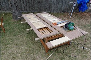
On the side by side couple of pages is a pictorial business relationship showing in sequence the different building stages. The images can be clicked on to go direct to the relevant page in the instructions.
On the page later on that are a few important explanations, followed by the plans, the materials list, and the step-by-pace building instructions with enough of pictures and drawings to help along the way.
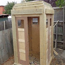
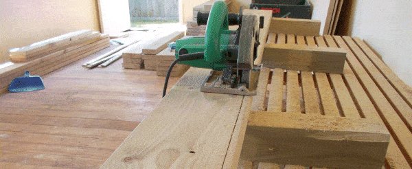
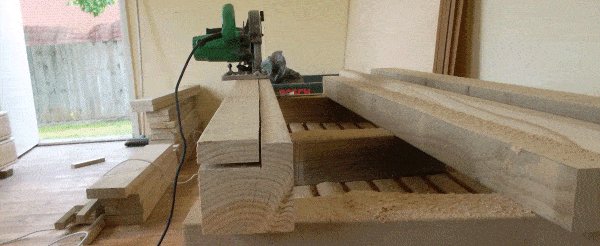
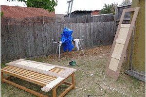
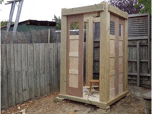
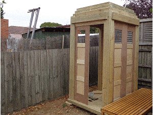
Photos of construction role 1
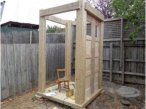
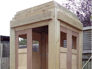
Photos of structure office 2
Explanations
An important annotation about the measurements used in this project
This projection is written in both Metric (mm) and Purple (inches).
Except for segments written separately for i system or the other, the metric measurements are given offset followed by the standard measurements in brackets ( ) – for case: 100 mm x 50 mm (2″ x 4″).
The metric (mm) measurements given are not an exact friction match to their equivalent imperial (inch) counterparts.
Why
Because similar common stock sizes vary (in actual, truthful sizes) from land to country every bit does availability of certain stock sizes. This project has been written accordingly.
This project uses common stock sizes available in Northward America (majestic version) and common stock sizes available in Australasia (metric version).
They are not the same in existent terms.
Other counties should be able to utilise ane system or the other – the signal is, use one system or the other. Do not combine the two considering they are not an exact match.
Example
A basic piece of 2-by-iv (100 mm 10 50 mm (2×4)) dimensional forest is actually 38 mm x 89 mm" (one½" x 3½) in existent size in North America,
simply…
In Australasia, the actual real size is more like 45 mm x xc mm (1¾" 10 3½").
Also,
Australasia has a common forest size that is around 35 mm ( 1⅜") thick. North America does not.
So there are some different wood sizes used in the metric version to that of the royal version.
To reiterate: The stock (bodily) sizes used in the metric version are different to those used in the purple (inch) version
Australasian stock availability and actual sizes are different to those in N America.
A TARDIS congenital using the metric measurements will be a slightly different size to the aforementioned structure using the royal (ft and in) measurements.
And so use one system or the other but don't mix and lucifer, i.e., do not combine the two systems.
Plans – Front, floor and footprint
Plans – Front height and floor
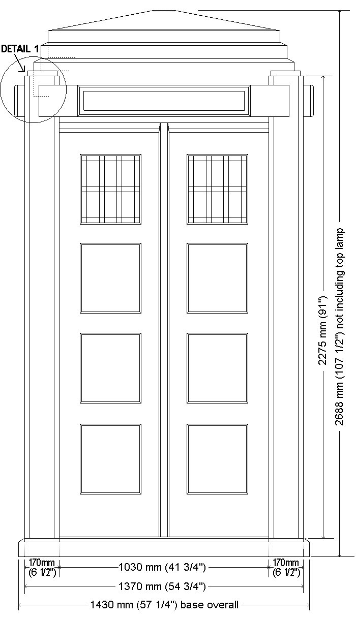
Notation: The metric (mm) measurements given are not an exact match to their equivalent imperial (inch) counterparts.
Refer to the 'Explanations' folio for further caption.
Plans – Footprint
Note: The metric (mm) measurements given are not an exact match to their equivalent imperial (inch) counterparts.
Refer to the 'Explanations' page for further explanation.
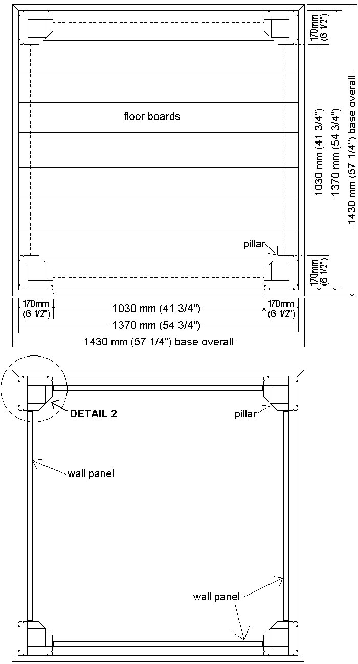
Plans – Base of operations, floor, and wall layout
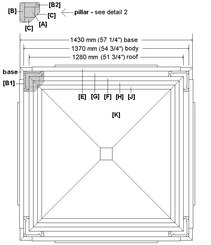
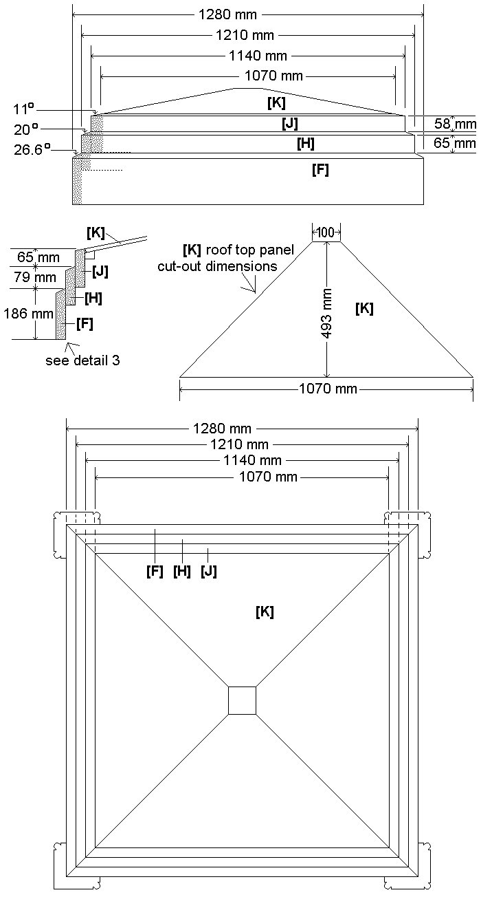
Plans – Top and roof (millimetres)
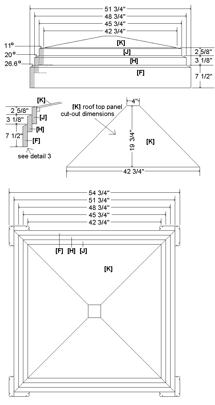
Plans – Meridian and roof (inches)
Plans – The sign

Note: The metric (mm) measurements given are not an exact match to their equivalent regal (inch) counterparts.
Refer to the 'Explanations' page for farther explanation.
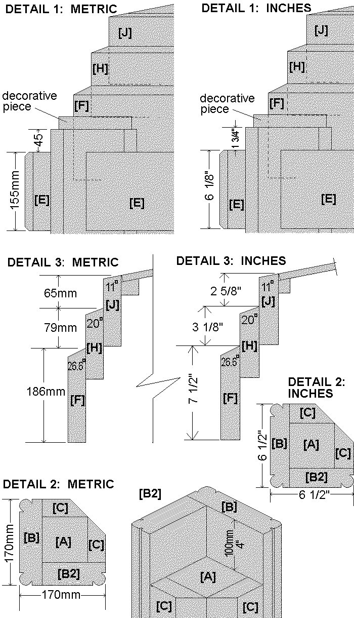
Plans – Details
Plans – Fixed walls – metric
Plans – Fixed wall – standard
Plans – Wall/door – metric
Plans – Wall/door – standard

Materials overall
Observe out the standard lengths of wood bachelor at your woods supplier and piece of work out how much you will need to get the cuts listed below. Your supplier could fifty-fifty do that for yous. Common standard lengths in some stores are 6 ft (1800 mm), viii ft (2400 mm), 10 ft (3000 mm), and 12 ft (3600 mm), 16 ft (4800 mm), and eighteen ft (5400 mm), merely these vary.
Note: The metric (mm) measurements given throughout this projection are not an exact match to their equivalent imperial (inch) counterparts. Use ane system or some other but don't mix and match.
Why? Go to the 'Explanations' page for an explanation.
Wood – metric
- xc mm 10 90 mm four @ 1430 mm, four @ 2175 mm
- 90 mm x 45 mm 1 @ 1250 mm
- 140 mm 10 45 mm 4 @ 2275 mm
- 190 mm x 45 mm iv @ 2275 mm, 4 @ 1030 mm
- xc mm x 35 mm8 @ 2175 mm
- 140 mm x 35 mm4 @ 1210 mm, iv @ 1140 mm
- 190 mm ten 35 mm4 @ 1230 mm, 4 @ 1280 mm
- 150 mm x 25 mm10 @ 1370 mm
Wood – standard
- 3½" 10 iii½" iv @ 57¼", 4 @ 87″
- 1½" ten iii½" 1 @ fifty¼", eight @ 87″
- 1½" 10 5½" 4 @ 91″, 4 @ 48¾", four @ 45¾"
- 1½" x seven½" iv @ 91″, 4 @ 41¾", 4 @ 49¼" , 4 @ 51¾"
- one″ x vi″10 @ 53¾"
PLYWOOD
- vi sheets of 1200 mm x 2400 mm (4 ft x eight ft) marine grade plywood (or other suitable for exterior use) a minimum of 12 mm (i/ii″) thick.
- Note: I used plywood 12 mm (1/ii″) thick considering of availability at the time. A thicker plywood, say fifteen mm to 19 mm (5/8″ to¾") would probably be ameliorate, though it's more expensive.
OTHER MATERIALS
- Galvanized bending fixing brackets: about 50 mm ten 50 mm x 50 mm (2″ 10 two″ x 2″) – 32 of.
- Wall summit trim: Shape out of 90 mm x 25 mm (1 x 3½") stock. Yous will need 4.8m (xvi ft) of.
- Mullions: shape out of 70 mm x 25 mm (one 10 2½") stock. You volition need 8 metres (28 ft) of.
- windows: acrylic, flashing tape (window bars), glue – refer to 'Step 12. Brand the windows.'
- Trim effectually the sign: Shape out of 38 mm x 18 mm (3/4″ x 1½") stock – yous will need 8 metres (28 ft) of.
Y'all volition also need an array of nails, screws, and gum.
Framing wood by section – metric
Note: The dimensions are given in bothmetric (this folio) andstandard (next page). Use one or the other.
For explanations on discrepancies between the two get to the 'Explanations' folio.
Annotation: Some stock sizes listed below are not common and therefore have to be ripped (cutting lengthwise) out of the standard sizes listed in the 'rip from' column.
In other words, rip (cut down lengthwise) the required 'size' from the 'rip from' size.
Metric measurements
| ID | REQ'D SIZE | RIP FROM | LENGTH | QTY |
|---|---|---|---|---|
| THE BASE | ||||
| xc mm ten 90 mm | 1430 mm | 4 | ||
| ninety mm 10 45 mm | 1250 mm | 1 | ||
| 150 mm 10 25 mm | 1370 mm | 10 | ||
| THE PILLARS | ||||
| [A] | 90 mm ten ninety mm | 2175 mm | 4 | |
| [B] | 170 mm 10 45 mm | 190 mm x 45 mm | 2275 mm | 4 |
| [B2] | 125 mm ten 45 mm | 140 mm x 45 mm | 2275 mm | iv |
| [C] | 90 mm x 35 mm | 2175 mm | 8 | |
| THE SIGN HOLDER | ||||
| [E] | 155 mm x 35 mm | 190 mm ten 35 mm | 1230 mm | 4 |
| THE INFILL | ||||
| [K] | 155 mm x 45 mm | 190 mm x 45 mm | 1030 mm | four |
| THE LOWER Head SIDES | ||||
| [F] | 186 mm 10 35 mm | 190 mm x 35 mm | 1280 mm | iv |
| THE Eye Caput SIDES | ||||
| [H] | 140 mm x 35 mm | 1210 mm | 4 | |
| THE UPPER Caput SIDES | ||||
| [J] | 140 mm x 35 mm | 1140 mm | four |
Framing forest by section – standard
Note: The dimensions are given in bothmetric (previous page) andstandard (this page). Use 1 or the other.
For explanations on discrepancies betwixt the two go to the 'Explanations' page.
Annotation: Some stock sizes listed below are not common and therefore take to be ripped (cut lengthwise) out of the standard sizes listed in the 'rip from' cavalcade.
In other words, rip (cut down lengthwise) the required 'size' from the 'rip from' size.
Standard measurements
| ID | REQ'D SIZE | RIP FROM | LENGTH | QTY |
|---|---|---|---|---|
| THE Base of operations | ||||
| iii½" x 3½" | 57½" | 4 | ||
| i½" x 3½" | l¼" | 1 | ||
| 1″ x 6″ | 54¾" | 10 | ||
| THE PILLARS | ||||
| [A] | three½" 10 3½" | 87″ | 4 | |
| [B] | one½" ten six½" | i½" x 7½" | 91″ | 4 |
| [B2] | 1½" x 5″ | 1½" x five½" | 91″ | 4 |
| [C] | 1½" x 3½" | 87″ | 8 | |
| THE SIGN HOLDER | ||||
| [E] | 1½" x six⅛" | 1½" ten seven½" | 49¼" | 4 |
| THE INFILL | ||||
| [G] | i½" x vi⅛" | 1½" ten 7½" | 41¾" | 4 |
| THE LOWER HEAD SIDES | ||||
| [F] | 1½" x 7½" | 51¾" | 4 | |
| THE MIDDLE Head SIDES | ||||
| [H] | 1½" ten 5½" | 48¾" | 4 | |
| THE UPPER Caput SIDES | ||||
| [J] | 1½" x 5½" | 45¾ | 4 |
Cutting list (frame)
Note: The dimensions are given in bothmetric andstandard. Employ one or the other.
For explanations on discrepancies between the two go to the 'Explanations' folio.
Annotation: Some of the common stock sizes below will need to be ripped (cut downward lengthwise) to obtain the required widths needed for this project (as in pace 2.).
Wood – metric
- 90 mm ten 90 mm 4 @ 1430 mm, iv @ 2175 mm
- ninety mm x 45 mm 1 @ 1250 mm
- 140 mm x 45 mm 4 @ 2275 mm
- 190 mm x 45 mm iv @ 2275 mm, 4 @ 1030 mm
- 90 mm x 35 mmeight @ 2175 mm
- 140 mm x 35 mm4 @ 1210 mm, 4 @ 1140 mm
- 190 mm x 35 mm4 @ 1230 mm, iv @ 1280 mm
- 150 mm x 25 mmten @ 1370 mm
Wood – standard
- three½" x 3½" 4 @ 57¼", iv @ 87″
- 1½" x iii½" 1 @ 50¼", 8 @ 87″
- 1½" x five½" 4 @ 91″, 4 @ 48¾", 4 @ 45¾"
- ane½" x seven½" 4 @ 91″, 4 @ 41¾", 4 @ 49¼" , 4 @ 51¾"
- 1″ x 6″10 @ 53¾"
Annotation: The metric (mm) measurements given are not an verbal lucifer to their equivalent imperial (inch) counterparts.
Refer to the 'Explanations' page for further explanation.
Allow'southward get started!
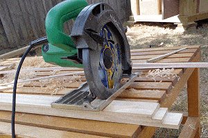
Step 1. Cut the frame pieces to length
- Cutting the frame pieces to the lengths as given in the tables below. There is both a metric tabular array followed past a standard (ft and inch) table.
Metric measurements (standard table next folio)
| FOR | STOCK SIZE | LENGTH | QTY |
|---|---|---|---|
| base border frame | 90 mm 10 xc mm | 1430 mm | 4 |
| [A] colonnade | 90 mm ten 90 mm | 2175 mm | four |
| base of operations center joist | 90 mm x 45 mm | 1250 mm | i |
| [B2] pillar | 140 mm x 45 mm | 2275 mm | 4 |
| [B] pillar | 190 mm x 45 mm | 2275 mm | 4 |
| [G] infill | 190 mm x 45 mm | 1030 mm | iv |
| [C] colonnade | ninety mm ten 35 mm | 2175 mm | viii |
| [H] eye head side | 140 mm x 35 mm | 1210 mm | iv |
| [J] upper head side | 140 mm x 35 mm | 1140 mm | four |
| [E] sign holder | 190 mm 10 35 mm | 1230 mm | 4 |
| [F] lower head side | 190 mm ten 35 mm | 1280 mm | 4 |
| floor boards | 150 mm ten 25 mm | 1370 mm | x |
Note: There are discrepancies betwixt the metric table on the previous page and the standard (ft and inch) table on this page. At that place is good reason for that, so use one or the other but exercise not mix and match – i.due east., stick to either the metric system or the standard system throughout the projection.
Some stock sizes vary between the two. Puzzled? For further explanation, go to the 'Explanations' page.
Standard measurements (metric table previous folio)
| FOR | STOCK SIZE | LENGTH | QTY |
|---|---|---|---|
| base border frame | 3½" X 3½" | 57¼" | 4 |
| [A] pillar | three½" Ten 3½" | 87″ | 4 |
| base middle joist | i½" X 3½" | l¼" | 1 |
| [B2] pillar | 1½" X 5½" | 91″ | four |
| [B] pillar | i½" Ten 7½" | 91″ | 4 |
| [G] infill | 1½" X 7½" | 41¾" | iv |
| [C] pillar | 1½" X iii½" | 87″ | 8 |
| [H] centre caput side | 1½" X 5½" | 48¾" | iv |
| [J] upper head side | one½" X 5½" | 45¾" | 4 |
| [Eastward] sign holder | 1½" X 7½" | 49¼" | 4 |
| [F] lower caput side | 1½" X vii½" | 51¾" | 4 |
| floor boards | 1″ X half-dozen″ | 54¾" | 10 |
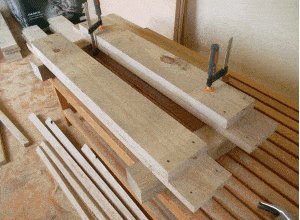
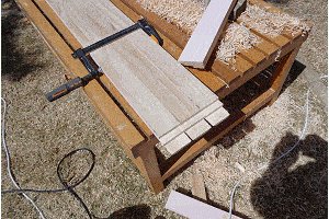
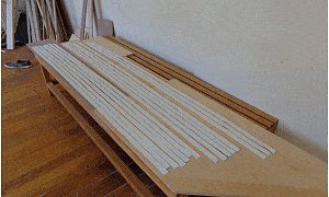
Step 2. Rip the relevant pieces to the required widths
- Rip (cut down lengthwise) the pieces that require ripping – namely pieces[B] pillar function,[B2] pillar function,[G]infill, and[Due east] sign holder.
- Rip to the widths given below.
Metric measurements (standard table beneath)
| PIECE | ORIG SIZE & LENGTH | RIP TO | QTY |
|---|---|---|---|
| [B] colonnade office | 190 mm x 45 mm past 2275 mm long | 170 mm wide | four |
| [B2] colonnade role | 140 mm ten 45 mm by 2275 mm long | 125 mm wide | iv |
| [G] infill | 190 mm x 45 mm by 1030 mm long | 155 mm wide | 4 |
| [Due east] sign holder | 190 mm x 35 mm by 1230 mm long | 155 mm broad | four |
Standard measurements (metric tabular array in a higher place)
| PIECE | ORIG SIZE & LENGTH | RIP TO | QTY |
|---|---|---|---|
| [B] pillar part | 1½" x 7½" by 91″ long | 6½" wide | four |
| [B2] pillar office | 1½" x v½" by 91″ long | 5″ wide | 4 |
| [G] infill | ane½" ten seven½" past 41¾" long | 6⅛" wide | 4 |
| [E] sign holder | 1½" x 7½" past 49¼" long | half dozen⅛" broad | 4 |
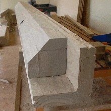
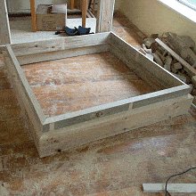
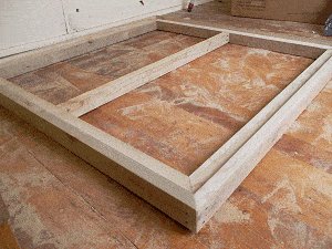
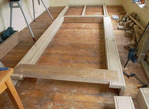
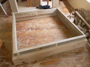
Step iii. Brand the base
- The base of operations consists of four pieces of ninety mm x 90 mm (iii½" x 3½") stock that are 1430 mm (57¼") long for the frame, 1 piece of 90 mm x 45 mm (1½" x iii½") stock that is 1250 mm (l¼") long for the middle flooring joist, and ten only 150 mm x 25 mm (1″ x 6″) flooring boards that are approximately 1370 mm (54¾") long.
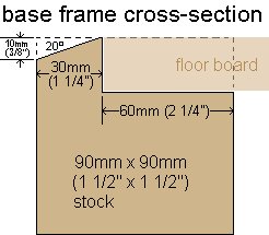
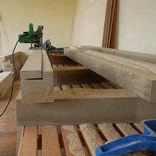
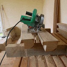
- 3.one. Make a rebate in the base of operations frame to take the floor boards. Refer to the 'base frame cross-section' motion-picture show.
- iii.two. Cut the ends of the base frame pieces inwards 45°. Ensure that the measurement along the rising of the rebate is 1370 mm (54¾").
- iii.three. Bevel the top border forth each frame member. Commencement the bevel 10 mm (⅜") downwards and run it up on a 20° bending. Sand all pieces.
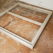
- 3.four. Assemble the floor base and add the eye joist.
- Do not add together the flooring boards merely yet,
Step four. Make up the pillars
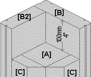
- Each pillar consists of a eye mail service[A] and surrounding pieces[B],[B2], & 2[C]south.
[A] is 90 mm x 90 mm (3½" 10 3½") stock 2175 mm (87″) long.
[B] is 170 mm x 45 mm (1½" x 6½") stock 2275 mm (91″) long.
[B2] is 125 mm 10 45 mm (1½" x 5″) stock 2275 mm (91″) long.
[C] is 90 mm x 35 mm (1½" x 3½") stock 2175 mm (87″) long.
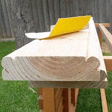
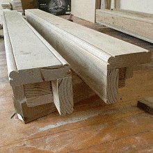
- Pieces[C] need to exist mitred (angled) 45° downwards one side, and pieces[B] and[B2]need to be shaped (round edges).
Shape the profile of pieces [B] and [B2]
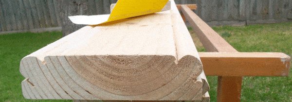
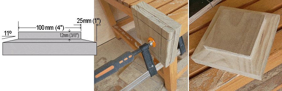
- 4.1. Make a 7 mm (5⁄xvi″) deep cut, lengthwise downwardly the face up and edge 25 mm in from the corner.
- iv.ii. Make some other cut 16 mm (⅝") in from the corner with the bract set on a 45° angle and the blade depth ready to 7 mm (5⁄16″) – catastrophe up with a trench the shape of half a 5.
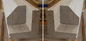
- iv.3. Circular the corners of[B] and[B2] with a planer and sand newspaper to attain equally almost as possible a 25 mm diameter round.
- Make up each corner colonnade of the Police Box past joining piece[A][B][B2] and ii[C]s.
Ensure one pair of corner pillars is made up in a mirror paradigm of the other pair.
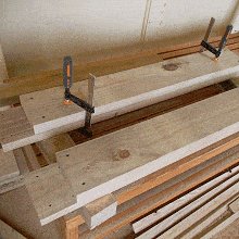
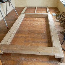
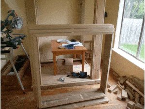
Step five. Assemble and stand up the frames
- Fix the infills[G] to the sign holders[East].
- On a flat surface, gather and set the front and rear frame units each consisting of two pillars, an infill/signholder slice, and a floor board.
- Then stand the front and rear frames units in place in the base of operations frame. Screw the floorboard of each frame unit to the base of operations frame and heart joist so that the screws can hands be extracted if the Police Box always needs to exist taken apart.
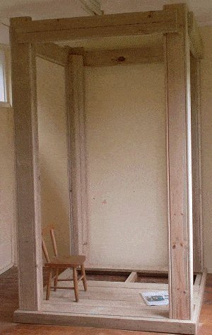
- Fix the side infill/signholder pieces to the front and rear frame units.
Screw the infill/signholder pieces to the pillars and so that the screws tin can easily be extracted if the Police Box ever need to exist taken apart. - Place and ready the remaining floor boards.
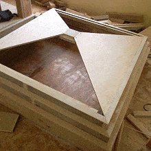
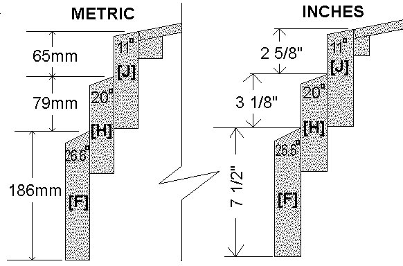
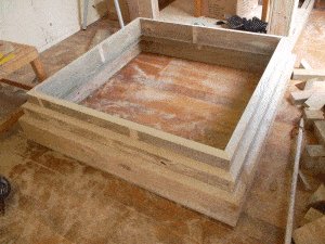
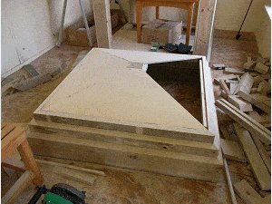
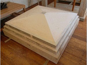
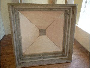
Step vi. Make the caput (pinnacle section)
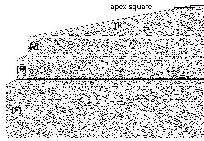
- The caput consists of the apex foursquare (a small shaped block at the very top), the roof panels[K], and 3 square box frames ([F],[H],[J],) that tin fit into one-another –[H] tin can fit into[F], and[J] tin can fit into[H].
How to make it: Angle-cutting along the top of all the frame side pieces as per the angles given below, and as well cut a 45° miter at the ends of each piece. The overall lengths are as well given below.
Lower head side [F] 1280 mm (51¾") OA (check on job, mensurate where information technology'due south to go in the frame structure). Cut a 26.6° angle along the peak.
Centre head side [H] 1210 OA (cheque, mensurate where it's to go in the lower head square). Cut a 20° bending forth tiptop
Upper head side [J] 1140mm OA (check, measure where it's to become in the middle head foursquare). Cut an xi° bending on top
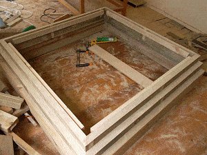
- Make upwardly the lower caput foursquare frame[F].
- Make up the middle head square frame[H] and fit information technology in the lower head square[F].
- Make up the upper caput square frame[J] and fit it in the middle caput square[H].
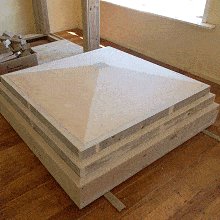
- Cutting and shape the apex square out of a block of forest approximately 150 mm (half-dozen″) square and 35 mm (1½") thick. Shape information technology as per drawing below.
- Fix a forest strip around the inside of the upper caput foursquare to sit down the roof panels on. Refer to the pictures below.
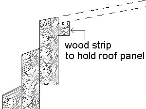
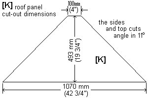
- Cut two roof panels 1070 mm (42¾") long x 493 mm (nineteen¾") high with the sides fishing in as shown in the drawing. Cut the sides and top and so that they angle inwards 11° – ie., have the blade on your saw tilted 11° while you brand the cut. (Check on task. Measure the actual required length along the lesser where the panel is to go and if necessary make adjustments).
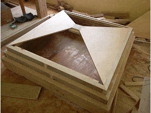
- Assemble two roof panels opposing one another with the bottoms sitting on the wood strips and the tops resting against the noon square. They will be self-supporting. Glue and set the panels to the apex square with a couple of screws at each coming together. Pre-drill the screw holes through the roof panels and screw down into the apex foursquare.
- Measure the other two panels on site, specifically the length along the lesser, up the sides, and along the top. Cut and fix in identify.
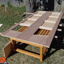
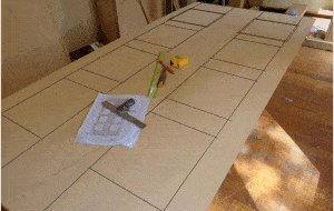
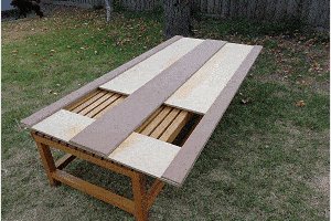
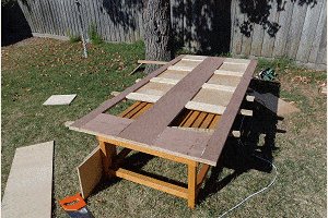
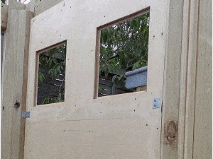
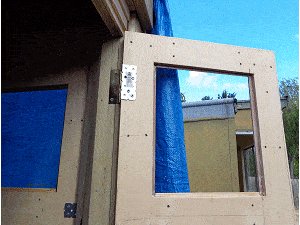
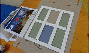
Step 7. Make the walls
- There are 4 walls. Three of them are identical, while the wall with the door differs.
- Each wall comprises of two sheets of plywood – i being the solid bankroll piece and the other being strips (stiles and rails) glued and screwed to the onetime.
- 'Stiles' are the strips that run vertically and 'rails' are the strips that run horizontally.
- Refer to the 'stock-still wall' and 'wall/door' plans for dimensions and follow the instructions below.
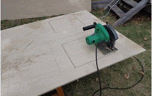
- Measure out and mark on the backing slice panels where the stiles and rails are to go – and from in that location you tin can determine the windows.
- Mark the window cut-out holes which will be 12 mm (ane/2″) bigger (all around) than the window markings.
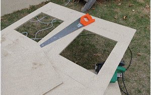
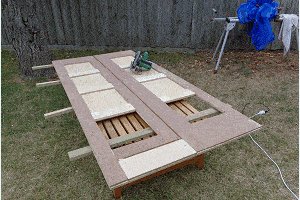
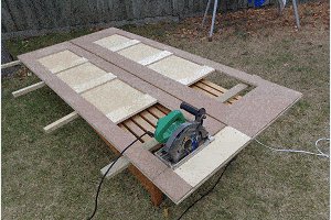
- Cut out the windows with a circular ability saw and a handsaw, or a jig-saw.
Cut the stiles, rail, and wall top trims
- Cut all the console stiles and rails including the angles (25°). Cut the stiles to length just cutting the rails oversize lengthwise. They can be measured and cut to verbal length once the stiles have been fixed in identify.
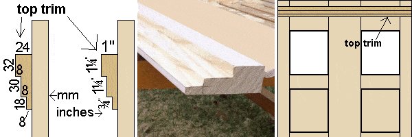
- Shape the tiptop trim as per plan. Overall the trim will be 24 mm ten 80 mm (one″ x 3¼") with steps cut in it. Refer to drawing.
Ready the stiles and rails to the backing panels
Note: The stiles are the strips that run vertically and the rails are the strips that run horizontally
- Gum the stiles to the panels and concord them there with a coupe of tacks (small nails, pins) so the panels tin can be turned over without the stiles falling off or moving position during the 'flipping' procedure.
- And then screw through the panels into the stiles, pulling all the components tightly together and letting the glue do it'southward piece of work.
- Flip the panels over again so the face is on meridian. Then cutting track to fit betwixt the stiles and fix them in the same manner equally the stiles were fixed. Sand all the panels.
- The layout of the panel with the door is unlike to that of the other three panels. Once this is sanded, cut out the door with a round saw and a handsaw and sand the freshly cut edges.
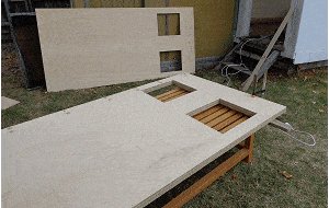
- These photos illustrate the explanations above.
Pace 8. Install the walls, caput, and door
Fix ane side wall and the front wall
- To merely i (for the fourth dimension being) side wall and the front wall (minus the door) add angle brackets, three to each side evenly spaced and a couple at the bottom. Refer to the pictures below.
- Fit one side wall (a removable wall, so practice not add together any mucilage or permanent fixings) and the front wall (less the door).
The forepart wall (minus the door) is a permanent fixture so gum can exist added.
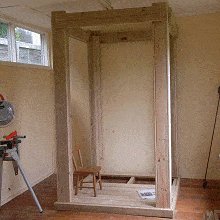
Drop the head in identify
- With 1 side wall and the front wall in place, the unit of measurement is adequately braced to take the head. Drop the head in place. It should fit neatly into the main body frame and sit on pillar pieces[A] and[C].
- Install the remaining two panels (walls) but get-go prepare them past adding the bending brackets (fixing brackets that necktie the panel to the corner pillars).
- Set up the side wall in identify without using any mucilage or permanent fixings and then it is removable. Fix the dorsum panel in permanently with both screws and glue.
Fix the top trims
- Cut to length and ready the top trims to the tops of the panels with gum and screws.
- Note that the two side panels are made to exist removable, so have care not to glue the trim to either the head or the side pillars. In other words, simply mucilage between the trim and the panel, as the trim will be fixed to the panel so when the panel is removed the trim will exist with information technology (and not stuck to the head or side pillars).
Door time
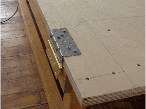
- Fix 3 90 mm butt hinges to the door.
- Because the screws are going into the sides of the plywood information technology is a practiced idea to comprehend the hinge office against the door with an angle bracket that could exist screwed into the side of the door as well as the back face. Have a wait at the picture below. The reason? I'm not 100% satisfied with the belongings power of screws screwed into the side of some plywood. Then hang the door.
Step 9. Shape and fix the mullions
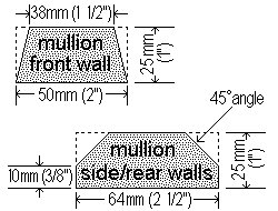
- The mullions are the strips of wood that run up the heart of the wall panels.
- Shape and fix the mullions. Refer to the cartoon for the profile.
- Rebate the top of the mullions to fit over the wall meridian horizontal trim. See the movie below.
- This can be done past mark the shape and then cutting out past cross-cutting multiple times with the ability saw bract set to the required depth.

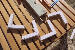
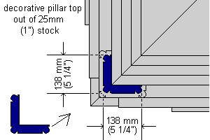
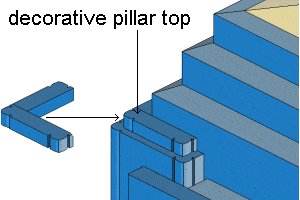
Footstep 10. Shape and fix the decorative pillar top pieces
- Shape, cut, and fix the decorative finishing pieces to the elevation of the outer pillars. These can be shaped in the same mode as the pillar pieces[B] and[B2] were shaped. Glue them to the elevation of the pillars BUT Not to the head, as the head is a removable item.
- Cut them out of 25 mm x 25 mm (i″ x 1″) stock.
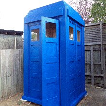
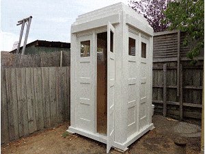
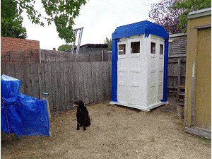
Step 11. Paint time
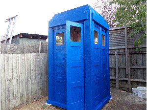
- Primer/sealer to the outsides and two coats of bluish.
- This part is best left to yous. You tin get all the information on the type of paint, applications etc. from your local pigment stockist.
The option of colour is besides upwards to yous. There are many different variations of blue used for both the Police boxes and the TARDIS props.
There does not seem to be a standard blue colour used for the many TARDIS props, so personal preference is probably the way to go.

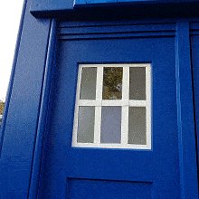
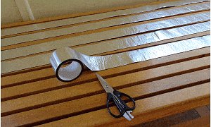
Step 12. Brand the windows

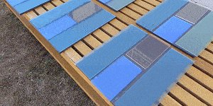
- There are eight windows to make up. Each window consists of four panes of plastic glass (acrylic canvass) – specifically two side pieces 103 mm x 350 mm (4⅛" x 14″) and two heart pieces 103mm ten 175mm (4⅛" 10 7″) with the top heart piece being clear and the residuum any color.
- The pieces are glued together and the joins overlaid with bars (strips) of 25 mm (1″) wide aluminium foil coated bituminous adhesive (flashing tape).
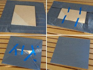
- Make a shine working platform – Using the plywood off-cuts from the window holes (8 in all), comprehend them with a thin plastic sheet (plastic rubbish bags will practise), fold the plastic underneath and hold it taut with record. This is to make a pad / backing lath so the window pieces tin be glued together on them. The glue will not adhere to the plastic rubbish bags – that is the purpose.
- Apply 3 mm (⅛") thick acrylic sheet (plastic glass) cutting to the following sizes and of varying colours:
- sixteen of 103 mm 10 350 mm (4⅛" 10 14″)
- 16 of 103 mm x 175 mm (4⅛" x 7″)
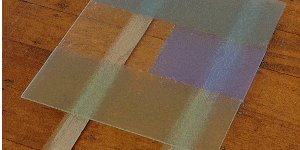
- Lay out the acrylic sheet pieces in sequence with virtually a 6 mm (¼") gap between them. Apply a sparse bead of glue (Anglosol 700) in the gaps and and so close the gaps. Because this glue is very powerful it can be harmful if non handled correctly – read the safety data notes that come with it or whatever like type glue used for butt joining acrylic sheet.
- Once all the sheets are glued, exit them for effectually 5 hrs, then take them off the backing boards (then the air tin can go to the underside) and place them on some sticks to let the mucilage harden more overnight.
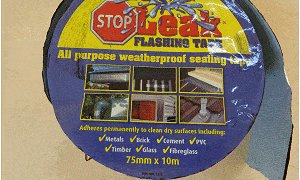
- Brand the bars for the windows from a curl of flashing record 75 mm (three″) wide by 10 m (33 ft) long. The tape is aluminium foil coated with a thick rubber/bituminous agglutinative. It tin be painted and is suitable for outside employ and sticks to just about anything.
- Cut the tape to workable lengths. The tape is easily cut with scissors or a craft knife. Using a pencil, mensurate and mark each length into three equal strips and cut them (past free hand) with a craft pocketknife to end up with strips 25 mm (1″) wide.
- So lay them on a apartment surface and paint them white with a roller brush. Apply two coats.
- Employ the adhesive strips over the joins of the window panes and around the edges. The windows are then ready to exist fitted.
- Run a bead of clear silicon sealant around the within of the window holes and fit the windows in place.
- Concur them in position with a few temporary small nails partly nailed in around the edges until the silicon sealant cures and glues the panes in place.
Step 13. Add the 'police phone call box' sign
- You volition need a 'police telephone call box' sign. Having a sign-writer do this for y'all is as good a way as whatsoever of getting it washed, unless you are able to exercise it yourself.
- On a piece of acrylic sheet approximately 3 or four mm (i/viii″ to 3/16″) thick have the sign prepared. Take that information beneath to the sign writer. You lot will need four signs.
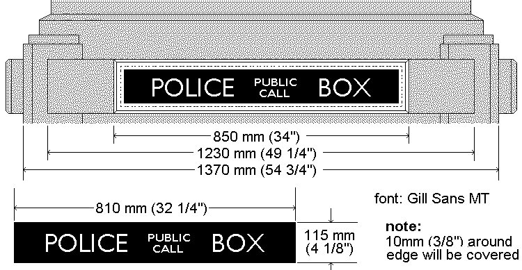
The trim around the sign
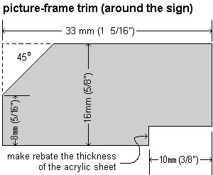
- Make and prepare 8 metres (28 ft) of trim to go around the 'police call box' sign. Shape according to the drawing.
- Once they are shaped, on a flat piece of work surface, cut to brand a picture frame around each sign. Pigment them.
- Then fix the sign and surrounding trim (picture frames) in place on the sign holder pieces[E]
Step 14. Final touches (almost)

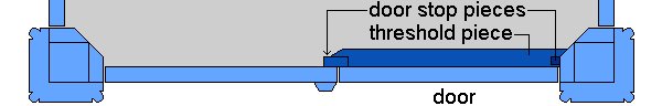
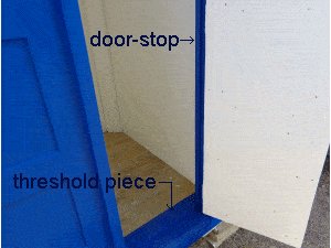
- Add together a door-cease around the door opening and a threshold piece on the floor that the door will close into. This is to stop pelting blowing or running in. Fix (approximately) 25 mm x 25 mm (one″ x 1″) wood upwardly the hinged side of the door opening frame and 25 mm 10 fifty mm (ane″ x two″) stock to the other side.
- Employ 19 mm x 50 mm (¾" x 2″) for the threshold piece. This is to stop rain-water blowing in and to give the door something to close against.
- You can probably get all of the above pieces from project off-cuts.
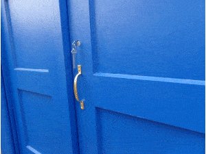
- Once the door-stops are in place, add a door handle and lock-set of selection.
Roof lamp Introduction
- This roof lamp is along the lines of the lamp that sits atop of the 1929 Mackenzie Trench blueprint constabulary box preserved at the National Tramway Museum in Crich, Derbyshire.
- It was, after all that police box that was the inspiration for The Doctors TARDIS.
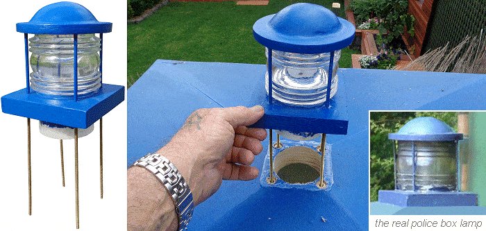
Description
- This roof lamp is basically a lamp container consisting of a fresnel lens sandwiched betwixt a cap and a square base piece.
- The base piece has a hole in the middle which accommodates a short piece of round PVC drain pipe.
- It is all held together with four threaded rods.
- The threaded rods protrude down past the square base slice in through the top of the TARDIS roof.
- From the inside, another square platform which carries the low-cal bulb and socket is added to the threaded rod.
- The light bulb fits upward through the PVC pipe into the fresnel lens. Information technology tin can be adapted upward and downwardly the threaded rod as need be.
- Once the lamp container is fixed to the TARDIS roof, the light is added (and adjusted) from inside the TARDIS box. That is very handy when a lite bulb need changing.
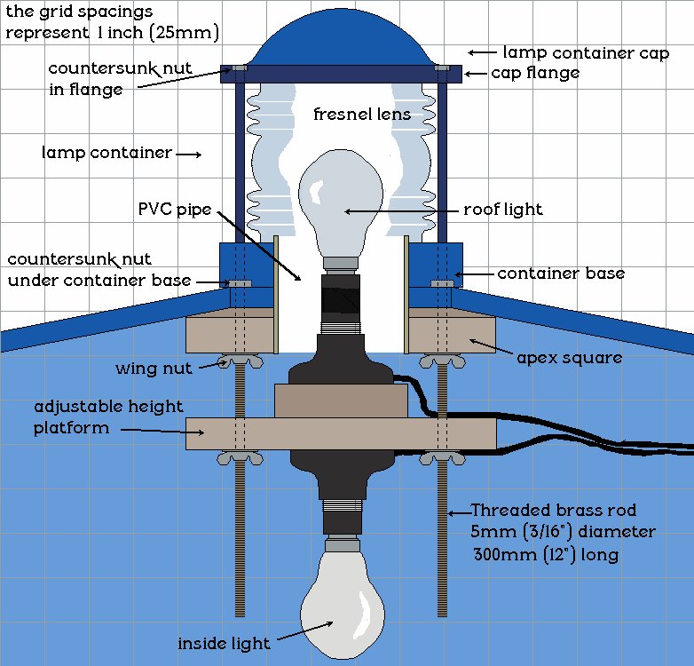
Roof lamp Plans
Note: The grid spacings in the drawing represent one inch (25mm).
Sourcing the components
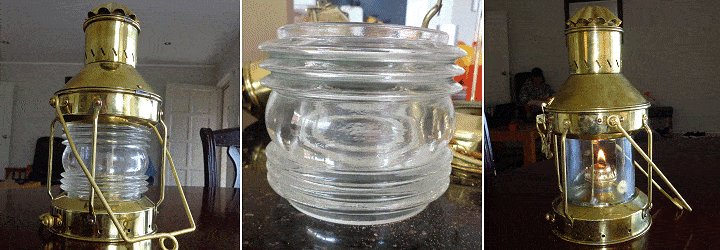
- The hardest office to find (for me, anyway) to brand this lamp, was the fresnel lens.
I eventually saw one in a send lamp (ballast light) that was sitting in the widow of a transport's chandler.
I purchased the complete lamp just to get the lens but the lamp was not wasted as I replaced the fresnel lens with evidently glass – simply a drinking glass jar (from the supermarket) with the bottom cut off. It worked perfectly and so I concluded upwardly with a working ships lamp too every bit a fresnel lens for the TARDIS project. - The fresnel lens was 106mm (iv 3/8″) outside diameter (at the widest part) and 90mm (three 1/2″) high.
The inside diameter was 76mm (iii″) one terminate and 78mm (a little over 3″) at the other stop. - All of the rest of the components I institute without too much trouble.
Note: Since obtaining the fresnel lens, I have seen others at various places online including ebay.
Overview
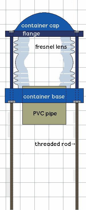
Notation: The grid spacings in the drawing represent 1 inch (25mm).
- The TARDIS lamp container consists of a fresnel lens sandwiched betwixt a cap and a square base of operations piece.
- The base of operations piece has a hole in the middle which accommodates a small slice of round PVC bleed pipe.
Information technology is all held together with iv threaded rods. - The container cap is a flange (round ring) with a dome in the centre.
- The flange is a ring, cut from a slice of plywood.
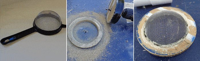
- The dome in the cap is a piece of dome-shaped wire mesh cutting out of a cheap kitchen strainer (sieve).
- The 'dome-shaped' wire mesh fits in the hole in the heart of the flange. It is held in place with a chip of glue.
- Fibreglass covers the cap.
- The threaded wire protrudes downward by the container base.
- The lamp container sits on top of the TARDIS roof and the threaded rod and the PVC pipe run through the roof.
- The lamp container is fastened from the inside of the roof and the light and lite platform is also fitted from the inside of the TARDIS.
The lamp container cap
- For the dome in the cap I used the wire mesh cut out of a cheap kitchen sieve. For the flange I cut a ring out of a piece of 10mm (3/viii″) thick plywood. I stuck the domed-shape wire mesh into the band and fibreglassed over it.
- Instructions follow.
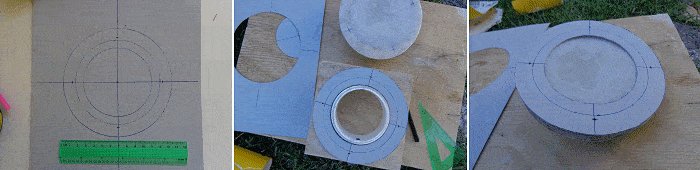
The flange
- Using a card board radial arm mark a circumference on a piece of 10mm (3/8″) thick piece of plywood with a diameter of 135mm (5 one/4″). Cut information technology out.
- Drill (or cut) a 105mm (4 1/8″) hole in the eye of it with a hole saw, jigsaw, or by whatsoever other means.
The dome
- Find an appropriate size cheap kitchen sieve (strainer).
- With a craft pocketknife cut the mesh from the handle. Push it (the mesh) into the flange hole then it protrudes 32mm (1 1/four″) through the flange.
- Use the plywood center off-cutting to hold the mesh against the flange. Sit it on a pillar (plastic container, jar, etc) and run a dewdrop of glue between the mesh and flange around the rim.
- When the glue has dried, tidy upward (sand excess glue) and with a craft pocketknife cut off any excess wire mesh on the underside of the lamp cap.
Fibreglassing the cap
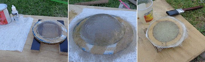
Fibreglass:
- Cut a piece of fibreglass mat big enough to cover the top of the lamp cap.
- Make up a mix of fibreglass resin and goad co-ordinate to the instructions on the can.
- Apply a coat of mix to the top of the cap, lay the mat over the top of the cap and saturate with more fibreglass mix.
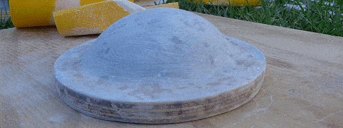
- The side by side twenty-four hour period cutting off the backlog fibreglass around the perimeter using a fine tooth saw or blade and sand paper.
Next fibreglass the underside of the lamp cap in the same manner. - The next day cut off the excess fibreglass around the perimeter using a fine tooth saw or blade and sand newspaper and give the complete lamp cap a sand.
The lamp container base
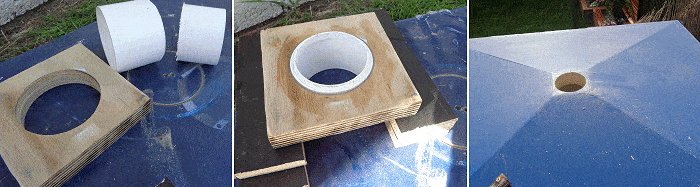
- For this utilize a piece of 24mm (1″) thick plywood 137mm (v 3/iv″) square. Maybe glue two 12mm (ane/two″) thick pieces together to get the required thickness.
- Also a short length about 64mm (2 1/2″) of PVC pipe with a diameter slightly smaller than the inside diameter of the fresnel lens. In this instance, 76mm (3″) diameter.
- Drill a 76mm (3″) bore hole in center of the plywood base piece and glue the PVC pipage in the hole, protruding 3mm (1/eight″) out the peak side and the residue hanging out the bottom. I used an agglutinative sealant that would grip to both the PVC and the forest.
- While waiting for everything to dry, drill a 76mm (3″) bore pigsty through the middle of the apex square at the top of the TARDIS.
- Make a hole template for the threaded rod. This is to marker all the necessary holes in the cap, base, roof, and light platform. Having a template ensures all the holes will be aligned.
- On a slice of card marker iii circles.
- 1 @ 86mm (3 3/8″) diameter – the overall width (bore) of the PVC pipe.
- 1 @ 106mm (4 1/8″) diameter – the overall width (bore) of the fresnel lens.
- 1 @ 135mm (5 5/16″) bore – the overall width (diameter) of the lamp cap
- Draw a cross from the middle and mark (on the cross lines) a point 3mm (1/8″) past the middle circumvolve (the overall width (bore) of the fresnel lens).
- Cut out forth the lines of the most inner and about outer circles and then you end up with a rim approximately 25mm (one″) wide.
That is the template to mark the holes for the four threaded rod pieces (the rods that concur it all together) on the cap flange, the base of the lamp container, the apex of the TARDIS roof, and the calorie-free socket support platform.
Threaded rod to the cap
- You will need iv lengths of Threaded rod, 5mm (three/16″) bore x 300mm (12″) long.
- Using the cardboard hole template, marker the holes for the threaded rod on the cap flange, the container base, and the apex of the TARDIS roof.
- Drill holes slightly bigger than the width (diameter) of the threaded rod through the pigsty marks.
Countersink to the depth of a nut, the top of the holes in the cap.
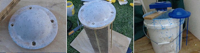
- Add a nut to one terminate of each of the iv threaded rods.
- Sit down the cap on acme of a prop of some sort to enable the four threaded rods to dangle, in one case they accept been inserted in the holes in the cap.
- Apply ample glue (fibreglass resin or like) around the nuts, and also in the countersunk holes.
- Gently turn and twist and motion the rods up-and-downward to enable the mucilage to seep around the rod and through every flake of the holes in the container cap.
- Wipe off excess gum and get out to dry.
- Once dry, sand smooth and pigment the cap, the base, and approximately 100mm (4″) of the threaded rods (the corporeality that will runs past the fresnel lens).
- Temporary tape the residual of the threaded rods and then as not to get any paint on that role. The function of the rods that go inside the TARDIS roof need to be kept make clean in society to take washers and nuts. In curt, don't paint whatsoever of the threaded rod that runs inside of the TARDIS.
Assemble the lamp container
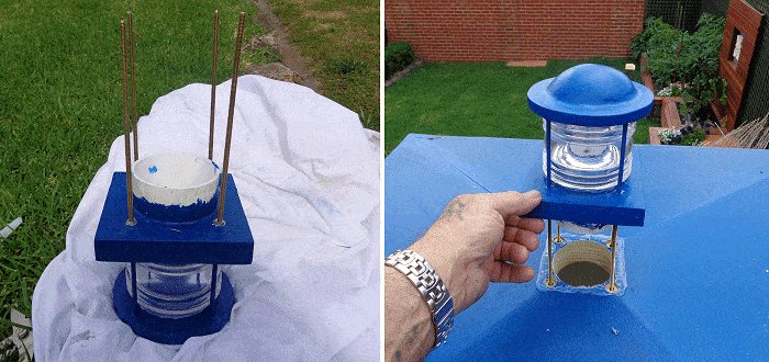
- When all is dry, assemble the lamp container – Add together a little sealant to the tiptop and lesser rims of the fresnel lens.
- With the container cap in upside-down position, place the fresnel lens in between the iv threaded rods and sit it on the underside of the cap, and then slide the base downwards the threaded rods until it sits on the other end of the lens. Remember, everything is upside down at the moment. Run into the picture to a higher place.
- Then place washers and nuts on the rods underneath the base and tighten them. Voila! The TARDIS lite container – all ready to place on superlative of the TARDIS roof.
- Countersink the meridian of the holes at the meridian of the roof to business firm the nuts and washers that are on the underside of the container base.
- The lamp container should at present fit neatly into place on top of the noon square with the excess threaded rod running through the noon foursquare into the TARDIS.
- Then identify washers and nuts on the rods underneath the noon square (from inside the TARDIS) and tighten them.
Put in a light or two
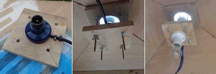
- So! You have the lamp container in place, now you need a light. At that place is a lot of backlog on the four threaded rods that hang inside the TARDIS.
- Make a platform (for the low-cal socket) like to the container base of operations – i.e., a piece of plywood 137mm (5 3/4″) square with 4 holes drilled to take the threaded rod, just the aforementioned equally the container base.
Fix an appropriate light socket in the middle of the plywood slice and have an electrician (or qualified person) wire information technology for you.
Put a light bulb in the socket and push the plywood slice upward (with the threaded rod going through the holes) until the light bulb sit at the required height inside the fresnel lens. Hold the platform in identify with fly-nuts underneath. - There! Piece of cake to adjust and easy to take out and alter the calorie-free.
- You tin also add together another low-cal socket to the underside of platform to light upwardly the inside of the TARDIS if and so required, although it would be best to run information technology off different ability wires so that both lights are contained of one some other.
The lights go on
waltonbarrispinks.blogspot.com
Source: https://www.buildeazy.com/london-police-box/